" /> My Title Skip to main content
#
Ashford Solutions LLC
Get Answers Now!

Free 30 minute consultation!

Speak with a developer to:

  • Examine your data acquisition\control requirements.
  • Discuss critical elements you may be concerned.
  • Explore acquisition hardware alternatives.
  • Help you define instrumentation requirements.
  • Discuss LabVIEW or other application frameworks.
  • Discuss how we can help you make it happen.

Additional live support or development available for a low hourly fee.

Click here to contact us.

Recent Projects
Advanced Nuclear Systems Engineering Laboratory

OSU : Advanced Nuclear Systems Engineering Laboratory (ANSEL)

DEVELOPED: Control Software - System Controls Multiple National Instrument's CompactRIO System, supporting hundreds of data acquisition channels. Graphical User Interphase employ's 6 displays and provides real-time information and control of High Temperature Test Facility

CHALLENGE:

This was an extremely complex project with hundreds of channels and very diverse data capture and performance requirements. A quick look at the ‘hardware used’ will give a sense of the scope and complexity our control software for this system had to manage and control with high accuracy and reliability. The Software also had to be extremely robust because of the extremely dangerous elements being controlled and monitored.

HTTF Website:
 

HARDWARE USED:

2   cRIO Equipment Racks (9024) with Embedded controllers

2   8 slot Expansion Racks (9144)

   47 Acquisition Cards Including: 

Thermocouple modules, Analog Input Modules, Digital IO and 4-20 ma Modules

Sensors included:

K and C Type Thermocouples, Gas Concentration Sensors, Custom Voltage Measurement Devices, Pressure Transmitters, Level Measurement Transducer, Turbine Flow Meter, Oxygen Transmitters, Watt Meters and High Current 3 phase SCRs. 

PROJECT OVERVIEW: The High Temperature Test Facility (HTTF) is a one-quarter scale test facility model of the Modular High Temperature Gas Reactor. The facility is capable of operation at 850°C (well mixed helium) with a maximum operating pressure of 0.8  Mpa . The nominal working fluid is helium with a heater power of approximately 600 kW although other gases can be used. The facility is configured to simulate a variety of postulated depressurized conduction cool down, pressurized conduction cool down and normal operations events. Specifically, the HTTF consists of:

• Vessel with 600kW electrically heated prismatic block core simulator

• Ceramic reflector and core regions

• Gas circulator

• Forced flow cavity cooling system

• Break valves

• Confinement simulation tank

• Instrumentation package

• Complete data acquisition system

Hydro-Mechanical Fuel Test Facility

OSU: Hydro-Mechanical Fuel Test Facility (HMFTF)

DEVELOPED: 

  • PXI chassis with 13 c-Series Modules
  • cRIO chassis with EtherCAT Expansion chassis provide additional 13 c-Series modules
  • Host PC also controls external PLC for water conditioning system using EthernetIP protocol
  • Replay Experiment option. All acquired data and user actions can be replayed for analysis.
  • Variable Acquisition Rate for 101 Channels.
  • Graph display allows the user to select any signal and show up to one hour of acquired data
  • Real Time Pump characteristics graphs
  • User Interface (pipes/valves/indicators) adjust to selectable Hardware Configuration
HTTF Website:

PROJECT OVERVIEW: The HMFTF is a testing facility which will be used to produce a database of hydromechanical information to supplement the qualification of the prototypic ultrahigh density U-Mo Low Enriched Uranium fuel which will be implemented into the U.S. High Performance Research Reactors upon their conversion to low enriched fuel. 

The current design of the HMFTF permits for hydraulic testing of a single full HPRR  element, and can simulate design basis accident conditions of all the U.S. HPRRs including operation between Lower Safety System Settings to Limiting Conditions of Operation.
 
Because the HMFTF’s purpose is providing hydro-mechanical information, its design has been limited to subcooled isothermal testing capabilities. Many unique challenges arise when designing a thermal-hydraulic test loop having such a wide range of operating conditions including mechanical configuration and sensing arrangement.
Aircraft Battery Test System
Project Name: Aircraft Battery Test System

CUSTOMER: Mobile Power Solutions,  Crane Aerospace

Web Site: http://www.mobilepowersolutions.com/

PROJECT OBJECTIVE: The customer needed to test a special type aircraft battery under a variety of environmental and load conditions. These tests also needed to run for months with little to no operator intervention. It was also critical that in the event of any problems the battery and test systems were placed in a known safe condition. So our objective was to define the hardware and software needed to accomplish this task and to then develop it for them.

HARDWARE CONTROLLED: The system employed a high current programmable load that was controlled by  application software via GPIB interface. In addition, the Battery was enclosed in a temperature chamber where it was both heated and cooled during the test cycles. The cooling was done by a dry air system using liquid nitrogen which was also controlled from the application program. (See Hardware configuration figure for more detail.

DEVELOPED: The test application program was developed using LabVIEW and included monitoring, logging, data display and alarm status reporting. (both on screen and by SMS Text messaging) We developed a scripting language for this application that would allow the definition of any number of test cycles and the respective test limits to be used. This allowed the customer to make last minute changes to testing cycles, durations etc. with no change to the test application program. The program also monitored the local uninterrupted power system so that emergency shutdown sequences could be initiated in the event there was a power failure.

CHALLENGES: As with any program there are always challenges that must be overcome. One aspect of this program was that it needed to be able to run for months at a time with no intervention required so it had to be very reliable and robust. This only comes from very detailed examination of the failure modes and how they will be trapped. There was also a need to log very large amounts of data and to manage this complexity in a way to minimize the users need to do so manually.

Click an image below to view larger

Cascade Microtech: Blueray Stage Characterization and Test System

CUSTOMER: Cascade Microtech

Website: https://www.cascademicrotech.com/products/probe-systems/200mm-wafer/blueray-series

PROJECT OBJECTIVE:  The customer wanted a program to automate the control of their newly designed wafer prober for detailed examination of accuracy and repeatability. This included a variety of moves of different distances and durations needed to perform a detailed analysis of the prober operation.

HARDWARE CONTROLLED: The prober platform was the PA200DS Blue Ray system. The program we developed needed to talk to several sensors to verify the stage position with a high degree of accuracy. One such device was the Optra Optical position sensor. We also recorded the position that the stage electronics was reporting along with 6 axis of acceleration data and several capacitive position sensors. (See program configuration diagram below)DEVELOPED: The application program we developed for this system was a LabVIEW application. The program was script based and thus allowed definition of all moves and data capture events that were to be performed. All sensor data was captured and logged for off line analysis.

Advanced Polymer Monitoring Technologies: APIC Intrinsic Viscosity Software

Advanced Polymer Monitoring Technologies Inc. (APMT): Intrinsic Software Project

CUSTOMER: Fluence Analytics, formerly Advanced Polymer Monitoring Technologies (APMT)

PROJECT OBJECTIVE: The objective was to develop software that would communicate, control and collect data from a custom Automatic Pulse Injection Characterization system designed specifically for measuring Intrinsic Viscosity of dilute polymer samples

Figure 8 Viscotek Viscometer System

HARDWARE CONTROLLED:

The system consisted of a WGE Dr. Bures Auto Injector, Pump and Viscometer configuration. The auto injector held a carrier sample vials containing various pre-made polymer solutions for analysis. These polymer samples were automatically cycled by commands from the Ashford Solutions developed application program via a USB Interface to the device. Data for each sample was automatically collected and analyzed at 5Hz and saved to tab delimited text files. Historical review and alternate analysis of data was handled through a custom designed interface.

DEVELOPED: Ashford Solutions developed a LabVIEW application program for this project that allowed the user to define how many experiments they wished to perform. The application then automated the capture and analysis of data from samples cycled by the Viscometer. The data was then presented to the user and the user allowed to interact with the captured data for further analysis as needed. The application was targeted at technicians rather than researchers and as such needed to be very user friendly as well as efficient and reliable for daily unattended operation.

Advanced Polymer Monitoring Technologies: SMSLS (Proto)

SMSLS Control and Data Collection Interface

CUSTOMER: Fluence Analytics, formerly Advanced Polymer Monitoring Technologies (APMT)

Website: https://www.fluenceanalytics.com/argen

: APMT: SMSLS System (Proto)

SMSLS PROJECT OBJECTIVE:

 The customer’s objective was to build a Simultaneous Multiple Sample Light Scattering (SMSLS) experiment platform that would automate running a variety of tests simultaneously and thereby significantly reducing the time to run a variety of tests this way. Ashford Solutions assisted in hardware selection and development of the LabVIEW application that controlled the system and provided the user interface for data capture and analysis.

HARDWARE CONTROLLED: The SMSLS hardware was entirely custom and consisted of 16 hardware sub-systems.

The hardware included the following:

  • 16 thermal control inputs/outputs for resistive heating elements
  • 8 thermal control outputs for thermoelectric cooling devices
  • 16 stepper\servo motor control channels to adjust Neutral Density filter selection
  • 12 stepper motor control channels for mixing control (8 dc motor control)
  • 2 CCD Camera image capture (USB 2.0 camera control channel)

DEVELOPED: Ashford Solutions developed the application software to control all these components in parallel. The application program controlled all the test hardware as well as captured data for all sub-systems. All data was continuously saved to independent tab delimited text files at up to 10 Hz sampling rate.

This project provided many interesting challenges due to the number of data acquisition channels and the desire to allow the user to examine and analyze historical data with the same application even as data capture was in progress. This required some special attention.     

Project Status: We are happy to report that the customer was able to commercialize this product from these early beginnings and now offers a refined version of this system to researchers all over the world.

Fluence Analytics: ARGEN System, Generation 1

Lumencor Light Engine Control Pod Project

ABOUT THIS CUSTOMER:

Lumencor is leading the life sciences with light engines for bioanalysis. Novel optical excitation subsystems are designed for an array of instruments including fluorescence microscopes.

Lumencor Pod Webpage: http://lumencor.com/products/other-accessories/controllers/

Lumencor Website: http://lumencor.com/

PROJECT OBJECTIVE: (in General)

The customer, Lumencor develops LED\Laser light sources that are used for bioanalysis and cases where the specific color spectrum and intensity of the light provided must be very controlled. The customer needed a controller that would allow a very simple way to control all their family of light engines from a single controller and with minimal complexity.

DEVELOPED:

Ashford Solutions designed a controller that employed two embedded processors, one Master which provided the user interface via a round graphical display, two buttons plus an optical encoder and managed the selection and control of the specific light engine to be controlled. The second Slave processor controlled all communications to and from the Light Engine and Host PC if connected.

Ashford Solutions in this case designed all the control electronics for the pod as well as wrote all the control firmware for both embedded processors which was developed using the C++ language on each..

CHALLENGES: There were many challenges with this product. There were design difficulties due to the specific USB Host controller chip we chose to use due to a defect in that part. We ultimately had to design around this to achieve the performance we required.

Lumencor Android Based Wireless Light Engine Controller

Lumencor Wireless Light Engine Controller

CUSTOMER: Lumencor Inc. (See previous Lumencor project for more info about this customer)

PROJECT OBJECTIVE: Ashford Solutions has provided development support to Lumencor for many of their products. In this case, they wished to control specific light engines from a tablet. (Android based) These Light Engines, supported Bluetooth interfaces and needed an application developed for the tablet to communicate with the Light Engine and allow real time enabling and control of light intensities.

DEVELOPED: Ashford Solutions developed several android applications using a language called Basic4Android to provide this control.

CHALLENGES: One challenge was the creation of software to allow auto paring of the light engine with the tablet as well as the challenge of keeping up with ever changing Android OS versions.

Android Based Tablet Light Engine Controller. Image to right is Customers Product Page showing the controler developed by Ashford Solutions.

SE Laboratories Test Automation Project

CUSTOMER: SE Laboratories

SE Laboratories Test Automation

PROJECT OBJECTIVE: (in General)

The customer, SE Laboratories, provides equipment and instrumentation calibration services and needed a way to automate the control of a very complex Tektronix TDS series oscilloscope, (TDS7104A). Their testing required them to setup very specific windows and conditions that would define the portion of a signal that they would capture. To make this more complex they wanted the scope to conditional be configured based upon other measurements it had taken in previous captures. This was to provide calculated limits based upon the standard they were testing against. They also wanted to the scope to display info about the Asset being tested, applicable regulatory standard, and other parameters during testing. This was all then to be captured. The scope Tektronix scope in this case provided a means to control almost every aspect of the capture and display via GPIB/SCPI interface.

CUSTOMERS’ STATED OBJECTIVES FOR PROJECT:

To build software driven platform that will allow a calibration technician do the following:

 Control Tektronix TDS series oscilloscope

♦ Send predefined setup configuration(s) to TDS7104A

♦ Send Screen Text to TDS7104A (Asset Number, applicable regulatory standard, and other parameters specific to test)

♦ Provide selection mechanism to allow selection of predefined 'canned’ text (txt or xml) and sending to oscilloscope

♦ Collect Data from TDS series oscilloscope

♦ Download and aggregate all reported data from TDS7104A for analysis

♦ Download Screen Waveform (in Color)

 Data Analysis

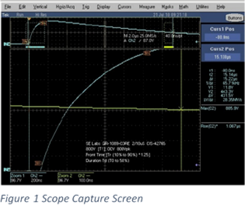
♦ Calculations made upon measured data to determine if unit is within specifications.

 Save Capture Data

♦ Save parametric data captured from TDS7104A in manageable data format (Excel, xml)

♦ Save Screen Waveform (in color) as .jpg file.

♦ Save Waveforms in folder reflecting asset number

♦ Sequential Waveform captures will be named as such (01.jpg, 02.jpg etc.)  

DEVELOPED:

Ashford Solutions developed a LabVIEW control application that fully configured and operated the TDS7104A Scope throughout the test sequence with little to no operator intervention other than setup and configuration of the device under test.

The test program loaded test scripts and configuration files that defined every aspect of the test and the various standards that applied and would be later used by the test to highlight ‘on screen’ out-of-spec test results when they occurred.

The application program was quite extensible and because it was table driven could be altered as the standards changed without having to change the program itself.

CHALLENGES:

Development of this application posed several complicated challenges. We had to become intimately familiar with and control of various functions of both this oscilloscope as well as the customers test system and complex test metrics.

Certification Matters

Ashford Solutions LLC
Aloha, Oregon 97078-2468
Phone: 503-217-2370
Email: Louis@AshfordSolutions.com

Certifications

National Instruments CLD

Build your own website
WebStudio Website Builder